Chirps Aren't Just for Birds and Bats (no bees)!
by Jon Adams N7UV
This is an attempt to show how chirps work to transmit data! Warning: This has nothing to do with APRS. There's a little arithmetic, but there are some big ideas. If you're interested in the way LoRa chirps generally work, read on!
LoRa is a well understood radio modulation technique whose technical characteristics have been documented publicly in a multitude of ways. It's really quite powerful, yet at the same time is at its heart pretty simple. While it's a form of FSK, it's quite novel compared to traditional FSK systems. There are two LoRa specific parameters that determine the basic waveform, the bandwidth (BW) and the spreading factor (SF). For this example, let's assume a center frequency (Fc) of 434.000 MHz. In the diagram below, an "up chirp" starts at the beginning of the symbol time (more on symbols later) and ends at the end of the symbol time. Using LoRa settings BW 125 kHz (0.125 MHz) and SF 7, the symbol time duration is 1.024 milliseconds (ms). (How'd I get to that number? Go here!) Thus, if "symbol start" is at time T = 0, "symbol stop" is 1.024 ms later.
In the diagram below, you can see that on the waterfall representation at the top the FM carrier sweeps linearly at time T=0 from 433.9375 MHz (434.000 MHz - 0.125 MHz/2) to 434.0625 MHz (434.000 MHz + 0.125 MHz/2) at time T = 1.024 ms, indicated by the big arrow pointing up and to the right. On an idealized spectrum analyzer representation at the bottom, the carrier is of constant amplitude, and it glides linearly from left to right over the symbol time. Heck, that's all a LoRa-type chirp is, a constant-amplitude carrier changing frequency linearly in a bounded frequency range! (Actual LoRa chirps are a bit more sophisticated, but at their heart they are constant-amplitude FM with a constant rate of change of frequency.)

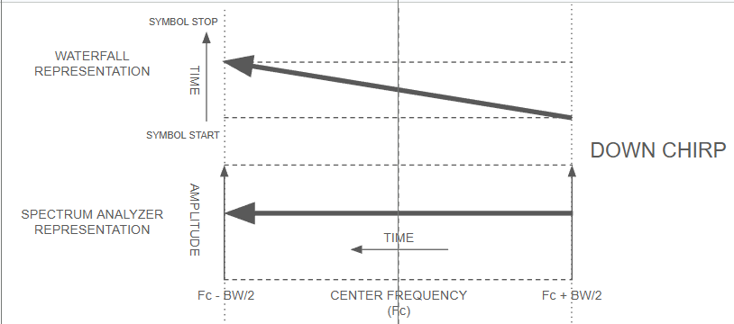
This up chirp could represent a "0" or a "1" bit, if we wanted. Let's assume it's a "1", then what's a "0"? In the simplest way, we could use the reverse of the up chirp, a "down chirp"!
The diagram below shows a down chirp, now with the symbol starting at time T=0 and frequency 434.0625 MHz and ending 1.024 ms later at 433.9375 MHz. Again, it's a constant amplitude carrier, this time descending linearly in frequency. Exactly the reverse of the up chirp.
Using these two symbols, the up chirp signaling a "1", and the down chirp signaling a "0", we could imagine sending the ASCII character "A" (hexadecimal x41, binary b01000001) using big endian (big-endian: most significant bit transmitted first, so read from the bottom up %^)
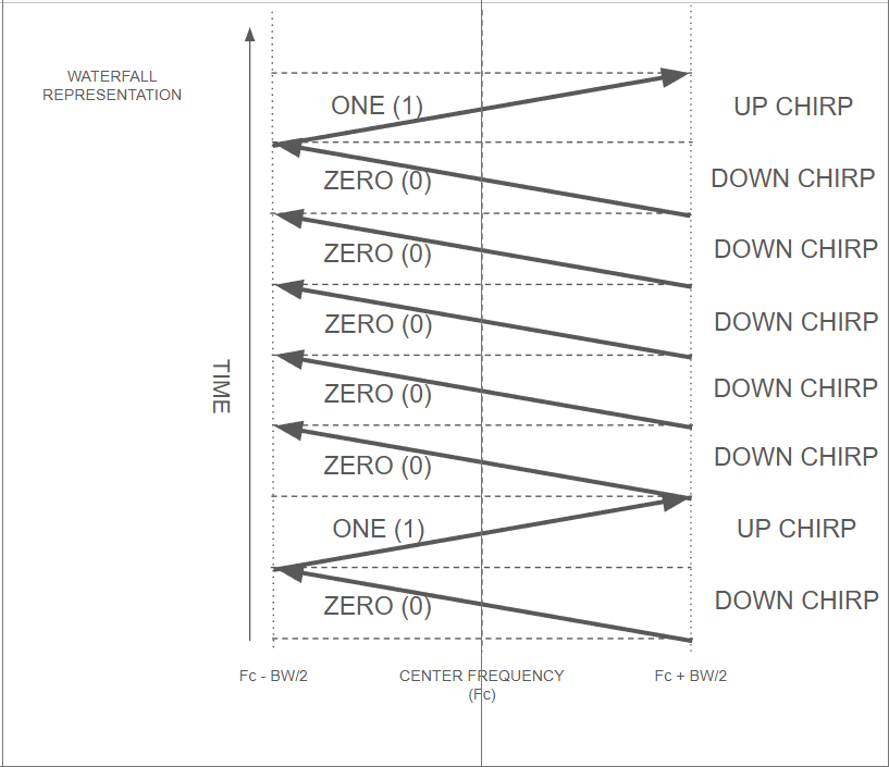
We just sent the ASCII letter "A" using chirps!!! If one were using this simple FSK pattern, the message ASCII "A" would be nearly obvious using just a fast waterfall display. Each of the above chirps are symbols that each encode a single bit of information.
What I just showed is a chirp encoding technique using up and down chirps, but LoRa is a bit more sophisticated. First, a LoRa frame uses nearly all up chirps - the only down chirps are in the preamble for frequency synchronization.
This is where symbols (instead of just bits) come into play. What we showed above (the ASCII letter "A" encoded with a series of up and down chirps) is hopefully helpful in terms of understanding how to use a chirp to send information. There are more clever and interesting ways to encode data onto a chirp, without blowing up the transmitter or receiver complexity, cost, and power consumption. And those are LoRa features.
The diagram below shows the same basic chirp pattern - it's a linear chirp, with a frequency/time ramp exactly the same as before, but now instead of always starting at Fc - BW/2, it starts at different precisely defined frequencies within its specified bandwidth, and this is where the term "symbol" becomes important. (I just realized it's kind of like pulse position modulation, except instead of being in the time domain it's the frequency domain, and the chirps are constant values in the rate of change of frequency per unit time way. It's a stretch.) The diagram shows a total of 4 different symbols, all individually recognizable on a waterfall display, each with identical slope, but each one is different in a simple yet important way as you may immediately realize.
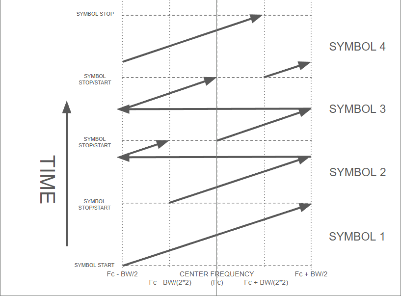
We can take these 4 different symbols and show that each one represents not just one bit, but two bits! (It's MAGIC %^) To symbol 1 (the first transmitted) we'll assign the bit pair "00" to, symbol 2 gets "01", symbol 3 is "10", and symbol 4 is "11".
Going back to transmitting the ASCII character "A", instead of 8 separate up and down chirps, all we need to do is transmit 4 symbols (with identical durations, the same bandwidth, just different starting points) and we get "01" "00" "00" "10". Doesn't take any longer to send, it's the same basic chirp. No down chirp required. Just up chirps with different but identical starting and ending points, or "phases", if you will. Remembering the earlier example with the center frequency set to 434.000 MHz, then symbol 2 above starts at time T=0 and frequency 433.96875 MHz, sweeps up to 434.06250 MHz, then phase continuously leaps back to 433.93750 MHz and completes its sweep at time T = 1.024 ms and frequency 433.96875 MHz, back to where it started.
You don't get nothing for nothing. So long as one stays in the same modulation scheme domain, being clever with how bits are encoded means a hit to link performance. Why does that happen here? Well, before, with just one bit per symbol, all we had to do was figure out if it was an up chirp or a down chirp. Easy! Could see it on the waterfall display! Now, while we have only up chirps, we have to discern the difference in where the chirp started/ended in frequency space. If either the transmitter or the receiver aren't at exactly the same frequency, or the sampling clock isn't quite synchronized (or a few other reasons) we could more might mistake most easily symbol 1 "00" for either symbol 2 "01" or symbol 4 "11". (It's a Hamming space thing.) A noisier channel will make it more difficult to hear exactly where in frequency domain the signal started.
Scaling from here, instead of a single symbol representing 2 bits, we could make that single symbol represent 3, 4, 5, or more data bits! Lora supports only the range from 5 bits per symbol to12 bits per symbol. Each time, using the same scheme as with 2 bits, we have to be more and more careful in where we start and stop the chirp while maintaining the linear slope, and making sure that the frequency jump that ensues is phase continuous (important to minimize spurious emissions and reduce the amount of energy wasted on those spurious emissions). Stable timing and frequency references at both ends are vital to make this work. A temperature-controlled crystal oscillator (TCXO) at both ends becomes really useful for both a stable clock and a stable frequency synthesizer. And happily, Semtech started including TCXOs in their packaged transceivers nearly from the beginning.
The example above showed how to encode 2 bits per symbol, but LoRa does way more - Lora allows from 5 to 12 bits per symbol! Holy cats, that's a lot. Each increase in the number of bits (N) encoded in a symbol means 2^N different symbols. That is, when we had one bit per symbol, it required 2 symbols (2^1 = 2). Two bits per symbol meant 2^2, or 4 symbols, just like shown above. For those 4 symbols, each different one started at either Fc - BW/2, FC - BW/4, FC, or FC + BW/4. The For LoRa's minimum of 5 bits per symbol, that means 2^5 (32) different symbols. SF12 would mean 4096 different symbols, all just a little different where they started in the frequency domain. Yeesh!
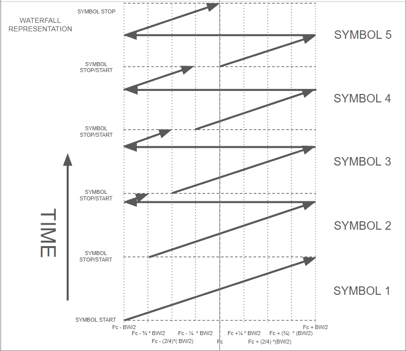
My drawing tool (Google Slides) is pretty poor, so drawing out a full set of SF5 symbols is hard. Instead, I'll do SF3 (not supported by LoRa) just to give everyone an idea of how each symbol differs from the next where slope (kHz/ms) is constant but the symbol starts at slightly different spots in frequency space (think of that as symbol phasing). Also, Google Slides sucks so much that I'm only doing the first 5 symbols of a theoretical SF3 symbol set. The main thing is that for this SF3 set there are 8 (2^3) possible symbol start frequencies. These are:
| Symbol # | Symbol Start Frequency | Bits |
| Symbol 1 | Fc - (4/4) * (BW/2) | 000 |
| Symbol 2 | Fc - (3/4) * (BW/2) | 001 |
| Symbol 3 | Fc - (2/4) * (BW/2) | 010 |
| Symbol 4 | Fc - (1/4) * (BW/2) | 011 |
| Symbol 5 | Fc + (0/4) * (BW/2) | 100 |
| Symbol 6 | Fc + (1/4) * (BW/2) | 101 |
| Symbol 7 | Fc + (2/4) * (BW/2) | 110 |
| Symbol 8 | Fc + (3/4) * (BW/2) | 111 |
And here's a waterfall diagram of the first 5 of those in order (read from bottom to top).
I know, TMI!
Again, what I've diagrammed above is very similar to how LoRa chirps work, but there are nuances that are just too much for today. Hopefully, what the above diagram and table show is that each individual symbol is differentiated from any other only by where the chirp starts and ends in frequency. Every chirp but symbol 1 above "wraps around" in frequency and completes its ramp at the end of the symbol time. Again, this is something the curious ham can see with a fast enough waterfall display, and can then read 3 data bits.
All this info comes directly from the voluminous technical literature that's publicly available. Not only from Semtech, but from multitudes of research papers (including a really good one for tracking rhinos entitled "Practical evaluation of carrier sensing for a LoRa wildlife monitoring network"), what other hams have done (the Sorrento (Italy) Amateur Radio Internode Mesh Network group has some really cool ideas!), and many many other sources.
Hopefully this makes sense - I write this in part to clear hand waves, assumptions, and cobwebs out of my own mind. Like Einstein (or was it Feynman?) was purported to have said, "if you can't explain it simply, you don't understand it well enough". What do you think? Is it simple enough? %^)
--Cheers and 73 - Jon N7UV